Assembly and control videos, plus student winding, printing, cutting, and vision-guided assembly projects. View evidence ↓
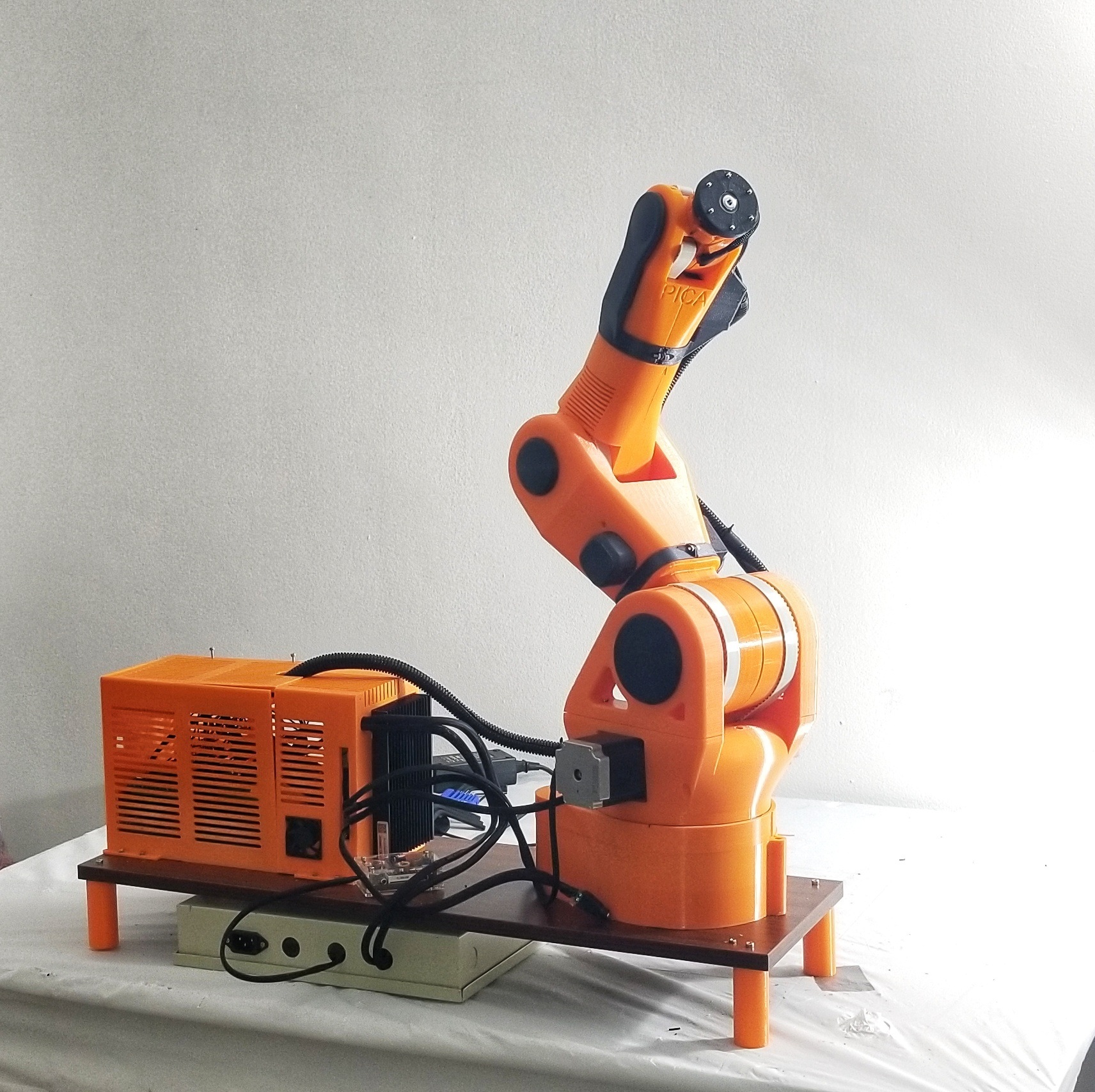
I designed this course around learning robotics by building a robot from individual components. Students assemble a desktop six-axis robotic arm by hand and use that process to understand its mechanics, calculate inverse kinematics, and develop motor-control algorithms. They then use the arm they built to create a fabrication or interaction application.
I independently developed and taught six offerings between 2021 and 2024. Online lectures and remote studio sessions connect mechanical assembly, Grasshopper modeling, electronics, programming, and project development. Students enter with Rhino and Grasshopper experience; the course introduces the programming needed to control their robot.
From components to a working robot
- Assemble. Build the base, arm, wrist, and end-effector mount from individual parts; install the servos and connect the control board. Assembly makes joint axes, link lengths, movement limits, and mechanical connections tangible.
- Model. Reconstruct the physical arm in Grasshopper. Use forward kinematics to relate joint angles to the tool pose, and calculate inverse kinematics to find joint angles for a target position and orientation.
- Control. Develop motor-control algorithms that translate joint angles into timed servo commands. Learn how serial communication and pulse-width modulation (PWM) connect the digital model to physical movement, then calibrate and test the assembled arm.
- Apply. Develop a fabrication or interaction application using the same robot. Design an end effector, plan its motion, test the process, and revise the hardware or control logic in response to the results.
Assembly from individual parts
Assembly footage shows the progression from loose components and servos to a desktop robotic arm.
Connecting geometry, electronics, and movement
Grasshopper motion control
A control demonstration connects the Grasshopper model with the assembled arm and its changing pose.
Testing the assembled arm
A second demonstration records the operator, controller, and robot together during motion tests.
Robotic winding: Traditional Yurt
Fall 2024 · Individual student project. Robotic Rhythms of the Traditional Yurt applies the assembled arm to winding twine around wooden frames. The student developed the kinematic model, planned winding points and sequences, and produced modules for a 1:100 pavilion model inspired by the structure of a traditional yurt.
The project records inverse-kinematics calculations, servo control, a threading-needle end effector, three winding patterns, and magnetic connections between modules. The final model brings the robot’s motion planning and a material assembly process into one design exercise.
Yurt project documentation
Five boards cover the design concept, inverse kinematics, assembly and motor control, winding sequences, and completed scale model. Click a board to enlarge it.
Interactive spatial winding
Fall 2023 · Individual student project. Spatial One-line Winding combines a desktop arm with a camera, fiducial markers, and a mobile control interface. reacTIVision identifies marker positions; Grasshopper translates the selected spatial points into robot motion; TouchOSC provides controls for the participant.
Participants guide a continuous thread around a field of vertical pins. The documented trials include a five-pointed star, a letter, a Tetris-like figure, an abstract portrait, and a rotating square, showing how one assembled robot can support different interactive making processes.
Spatial winding documentation
The setup, vision and interaction workflow, joint assembly, and five participant trials.
Human–machine interaction for 3D printing
2022 · Individual student project. Robotic Fabricator: Human–Machine Interaction develops a robotic printing setup with an E3D printhead, a custom mount, and a mobile augmented-reality interface built with Fologram.
The student connects toolpath generation and joint control with separate systems for material feeding and temperature control. The interface allows the user to preview geometry and modify parameters, while the project boards document the mechanical assembly, electronics, and physical setup.
Interactive printing documentation
Printhead design, toolpath control, material and temperature circuits, and the augmented-reality interface.
Computer vision and block assembly
2022 · Individual study. Re-order Construction connects a camera and OpenCV image processing to a robotic arm equipped with a suction tool. The student investigates how the robot can identify the position and orientation of scattered pieces, then use Grasshopper-based motion planning to place them into a stacked assembly.
The boards document image-boundary tests, pose extraction, inverse kinematics, robot construction, and physical stacking experiments. A proposal for assembling traditional timber components extends the study beyond the desktop trials.
Vision-guided assembly documentation
Computer-vision workflow, camera and suction-tool setup, component recognition tests, and stacked models.
Tool testing, foam cutting, and vault models
2021 · Individual student project. Robotic Arm Democratization follows the robot from initial writing tests through end-effector development and fabrication trials. The student tests a crayon, suction gripper, 3D-printing pen, and electric foam-cutting tools, then adjusts the model and tool orientation in response to alignment errors, servo play, limited joint travel, and tool weight.
The final design studies a vault generated with RhinoVault. Robotic foam cutting and plaster casting informed the experiments; the final panelized vault model was laser-cut because the student encountered time and servo-accuracy limits. A 3D-printed reference model supports comparison with the original curved form.
First drawing tests
The assembled arm follows a drawing path, providing an initial test of tool position and control.
Robotic foam cutting
A modified electric cutting tool is mounted on the arm and tested on a foam block; the video also shows the resulting cut surface.
End-effector and fabrication documentation
Writing, tool tests, calibration, foam cutting and casting, vault design, and comparison of the laser-cut and 3D-printed models. The robot's assembly and control board appears above.
Related independent study: Nutri-Print
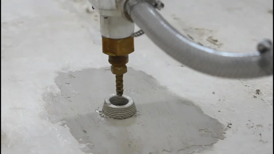
This separately mentored food-printing project extends the relationship between fabrication tools and interaction design. Nutri-Print proposes an app for customizing meals and sharing recipes, connected to a food-extrusion workflow.
The documentation brings together user research, interface prototypes, ingredient and nozzle tests, printer mechanics, G-code, and printed food patterns. It is presented here as a related independent study using a food printer.
Nutri-Print documentation
An independent mentee project connects an app concept with food-printing experiments and process documentation.