A 90-layer planning example reports 91% less wiping material; a separate 45-layer print tests graded composition. These are different demonstrations. View evidence ↓
Three-dimensional printing results
A 90-layer planning example on a 300 × 300 mm bed uses 8 wipe units. Compared with a tower requiring at least one unit per layer, the paper reports 91% less wiping material, 11% less total material, and 13.8% less travel time for that example.
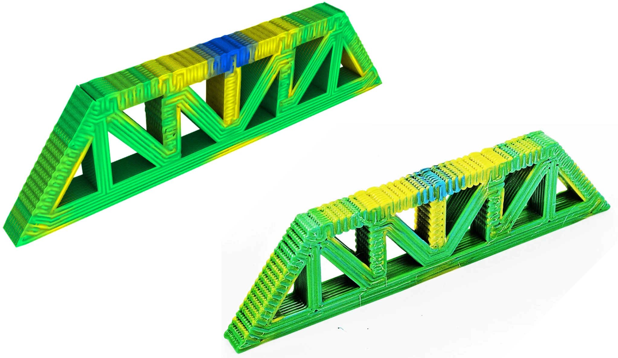
A separate 45-layer printed specimen maps local overhang to a gradient palette across porous Schwarz P cells. The comparison shows the sampled field, predicted extrusion, and physical print, with the transition waste collected beside the object.
The 45-layer thermoplastic specimen: local-overhang sampling and toolpath visualization (left), with the printed porous cells and wipe units (right).
Two-dimensional printing: soft and hard boundaries
Parallel zigzag paths carry repeated material transitions across an image, producing a directional blur. The hard-edge method fills each material region before moving to the next. Circle packing and an alpha-complex graph support a continuous path through each region; the regions are then connected to reduce material changes.
The 200 × 200 mm prints compare both strategies using a posterized Mona Lisa image. Their different edge qualities arise from the relationship between path direction, transition length, and the order in which material regions are filled.
Physical 200 × 200 mm prints: soft-edge parallel filling (left) and hard-edge alpha-complex filling (right).
Composition and continuity in one workflow
Changing a nozzle’s input mixture does not immediately change the material leaving its tip. Material retained in the mixing chamber delays and blends each transition, while disconnected print regions introduce travel moves and additional material changes. The workflow coordinates mixture assignment, transition compensation, and the order of extrusion paths so these effects can be planned together.
Implemented in Ovenbird for Rhino and Grasshopper, it converts three-dimensional models or posterized images into material-coded toolpaths, predicts the resulting gradients, and exports machine instructions.
The 3D workflow assigns mixtures to a sliced model; the 2D workflow connects paths within image regions. Both pass through transition adjustment and visual inspection before G-code export.
Modeling the material transition
Each mixture is stored as a vector of input-material fractions; the collection forms a reusable palette. The nozzle response is modeled as a moving average with a lag, with delay and transition lengths calibrated from extrusion tests. Advancing the commanded mixture change aligns the midpoint of the predicted transition with its intended position.
Changes spaced more closely than the transition length blend together before the nozzle reaches the requested mixture. Longer gradients can be constructed from intermediate palette entries.
Predicted input and output compositions: delay compensation, consecutive mixture changes, extended gradients, and color blending across a palette.
Assigning mixtures to geometry
The toolpath stores each segment by layer, curve, and segment, with an associated mixture index. Explicit boundary objects split paths into material regions; sampled fields assign mixtures from values such as local overhang or structural response. Continuous values are mapped to the nearest palette entry, and neighboring segments with the same assignment are merged.
Layer–curve–segment indexing and alternative material-assignment methods (left); Ovenbird components and a Grasshopper workflow (right).
Keeping material changes out of the printed body
For a closed curve, the planner places entry and exit within the same material region. It then uses a greedy sequence to print as many compatible curves and layers as possible before changing that transit material. The algorithm reduces wiping stops without claiming a globally optimal sequence.
Separate wipe units collect transitions when a change is required. Clearance between the print and wipe zones lets the extruder reach the bed without colliding with the growing object, so wipe units do not need to rise to the current print height.
Actively mixed filament and paste extrusion concepts (left); separate print and wipe zones with extruder-clearance allowances (right). The experiments presented here use thermoplastic filaments.
Experimental scope
The printed demonstrations use thermoplastic filaments, mainly PLA. Extension to paste extrusion and architectural-scale production requires further testing of material compatibility, deposition accuracy, and transition behavior. Color is used to inspect material distribution; the examples do not establish mechanical performance gains from the gradients.
Related publications
All publications →-
Accepted for ACADIA 2026 · Conference in October 2026
As-Continuous-As-Possible Multi-Material Extrusion with Gradient Composition and Transition