An 18 mm command advance aligns the tested interface; a printed truss reaches 1.16 kN versus 0.83 kN for its control. Both results are setup-specific. View evidence ↓
Locating the intended interface
The calibration test prints a 200 × 50 mm zig-zag pattern with a 2 mm extrusion width and a 0.8 mm layer height. Without an advance, the observed interface falls beyond the intended boundary. A 30 mm advance overcompensates; an 18 mm advance aligns the visual breakpoint for this tested setup.
The 18 mm value is an empirical calibration for these materials and printing conditions. Treating the delay and transition as fixed path lengths assumes a fixed extrusion cross-section and flow condition, with materials of similar viscosity.
Discrete patches: assigning material by structural demand
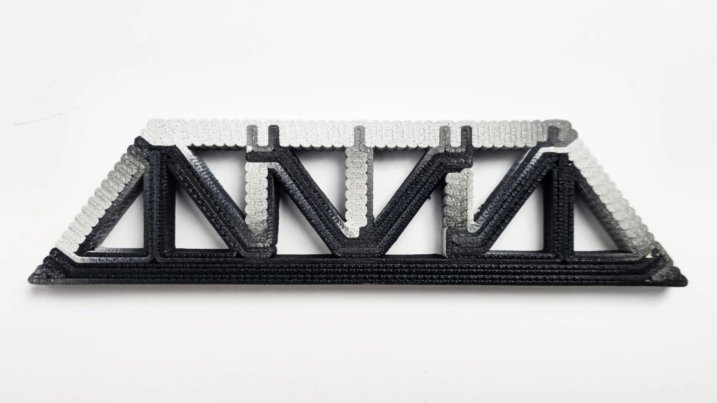
A pair of 250 × 65 × 16 mm Pratt trusses tests material assignment under three-point bending. The multimaterial specimen places carbon-fiber-reinforced PLA in tensile members and white PLA in compressive members. The control uses white PLA throughout. Both are printed at 30 mm/s with a 0.8 mm layer height and a 2 mm extrusion width, then tested over a 220 mm span.
The multimaterial specimen reaches 1.16 kN, compared with 0.83 kN for the control, while weighing 166 g rather than 179 g. The paper reports approximately 67% greater toughness from numerical integration of the bending response. These results describe the tested pair of specimens; buckling of a compression member governs the observed deformation.
Material distribution as a design input
A component can demand different material behavior at adjacent locations: a stronger tensile member, a lighter infill, or a gradual transition between regions. This project treats that spatial distribution as an input to fabrication. Its central measure is material fidelity—how closely the composition and location of deposited material follow the design.
The Single-Nozzle Multi-Filament (SNMF) system combines multiple filament feeds in an actively mixed extrusion head. Programmable feed ratios create continuous changes in composition within one printed object.
The research joins three parts of the problem: a four-filament printhead with active mixing, a numerical model of the delay between commanded and deposited composition, and design methods that attach material information to toolpaths. Together, they make both a mixture and its position programmable within a continuous print.
The computational workflow supports three representations of material intent. Image sampling maps pixel values to composition. Discrete patches assign material to regions in a plane. Surface division organizes composition over three-dimensional geometry. Each representation becomes a sequence of fabrication instructions.
Developed at the University of Pennsylvania’s Polyhedral Structures Laboratory, the study was published by Teng Teng, Yefan Zhi, and Masoud Akbarzadeh in Materials & Design 249 (2025), article 113479. The experiments below trace the workflow from material recipes and calibrated transitions to image patterns, structural regions, and three-dimensional surfaces.
Method
The SNMF system connects representations of material distribution to a model of mixing inside the nozzle. Feed commands can therefore account for the transition between intended and deposited composition.
- 01
Represent
Assign material composition through image sampling, two-dimensional patches, or three-dimensional surface division.
- 02
Model
Describe the material transition inside an actively mixed extrusion head.
- 03
Control
Translate spatial composition into coordinated filament-feed and extrusion commands.
- 04
Test
Compare deposited transitions and printed case studies with their intended material distributions.
Calibrating the translation into matter
Material already inside a nozzle continues to influence the output after a feed ratio changes. A numerical model describes this transition, while experiments relate feed commands to deposited composition. Accounting for this behavior is necessary to locate an interface within the printed geometry.
The model separates two distances along the deposited path. The delay length, L₁, runs from a change in feeder commands to the first appearance of the new material. The transition length, L₂, covers the subsequent change in composition. A linear approximation places the visual midpoint at L₀ = L₁ + L₂/2 after the command.
Advancing the feed change by L₀ moves the deposited midpoint toward the intended interface. A moving-average formulation extends the model to repeated switches and multiple materials, allowing the software to preview the effect of the mixing chamber before printing.
Comparing designed and deposited gradients
A 200 × 100 mm sample tests ten programmed mixtures of red and green PLA. The study compares the toolpath visualization with the printed sample by extracting average red and green intensity profiles along the images.
The profiles follow the overall intended gradient, with a substantial green-channel deviation and a smaller red-channel deviation near the beginning. Agreement improves through the middle and final regions. The intensity profiles quantify visual agreement between the design and print and reveal where blending control still needs refinement.
Active mixing in a four-filament printhead
Four independently driven filament feeds enter a shared, heated aluminum-alloy nozzle. A motor-driven, 2 mm tungsten-steel auger mixes the molten materials in the output chamber. Changing the relative feed rates changes composition; coordinating the total feed and auger rotation sustains extrusion along the toolpath.
The modular assembly combines filament feeders, heat breaks, a cooling tower, and a heated mixing chamber on a CR-10 three-axis gantry. The chamber has a 2 mm diameter and a 5 mm length. This finite volume matters: material remains inside the head while the input ratios change, so the output records a history of earlier commands.
Active-mixing extrusion system
Extrusion-head components and the integrated printing platform.
Active mixing in operation
A short demonstration of the printing system.
Programming material profiles
A material profile stores the fraction of each input filament in a mixture. Two filaments can therefore supply more than two printable compositions: black and white PLA, for example, produce four grayscale profiles with ratios of 1:0, 0.7:0.3, 0.3:0.7, and 0:1.
Custom software associates these profiles with segments of a curve and translates the result into G-code. The modified Marlin firmware uses M163 to assign feeder weights, M164 to store a mixture, and tool-selection commands to recall it during motion. The selected tool index identifies a material recipe within the same printhead. Coordinated feeder speeds then deliver that recipe while the auger maintains extrusion.
Auger speed changes the material transition
Two experiments isolate different consequences of active mixing. With red and blue PLA of similar viscosity, speeds of 50 and 75 rpm produce longer, smoother transitions; 125 and 150 rpm produce sharper transitions, with 100 rpm between them. These samples use a 0.8 mm layer height and a 3 mm extrusion width.
A separate series prints 200 × 19 × 4 mm strips transitioning from white PLA to black TPU at 170, 200, 240, and 270 rpm. In the reported tensile tests, 170 rpm gives the highest peak stress, followed by 200 rpm; the 240 and 270 rpm specimens show lower strength and stiffness. The two series connect auger speed to visual transition length and mechanical behavior under their respective material and process conditions.
Printed objects and material distributions
Six case studies connect the method to different shapes and functional requirements, including structural specimens and objects with graded material properties. The related truss and insulation studies examine how material assignment can respond to force flow and thermal demand.
Structural specimens, graded surfaces, and image-based material placement use three ways of assigning composition: sampling an image, partitioning planar regions, and dividing a three-dimensional surface. The same material-profile and transition-control workflow connects these representations to fabrication.
Image sampling: four grayscales from two filaments
The Mona Lisa study converts an image into a monochrome bitmap and quantizes it to four grayscale levels: 0, 0.3, 0.7, and 1. Each level maps to a black-and-white PLA mixture. Sampling along a continuous zig-zag path assigns the appropriate mixture to each segment.
The 12 × 12 cm print uses 2 mm path spacing. Its image is formed by changes in the deposited blend, connecting pixel values, material recipes, and physical resolution in one fabrication sequence.
Connecting stress regions into a continuous path
An intricate strut-and-tie example begins with four loading points and two supports. Algebraic graphic statics and layout optimization identify tensile and compressive regions. Toolpaths run parallel to the tensile stress directions and perpendicular to the compressive directions, then connect through local detours and crossings into a continuous zig-zag path.
This specimen uses carbon-fiber-reinforced PETG in tensile regions and white PETG in compressive regions. Its material system differs from the PLA pair used in the bending comparison above. The path visualization and fabricated object document how the regional assignment survives the transition from structural model to print.
Surface division: a funicular structure within a continuous shell
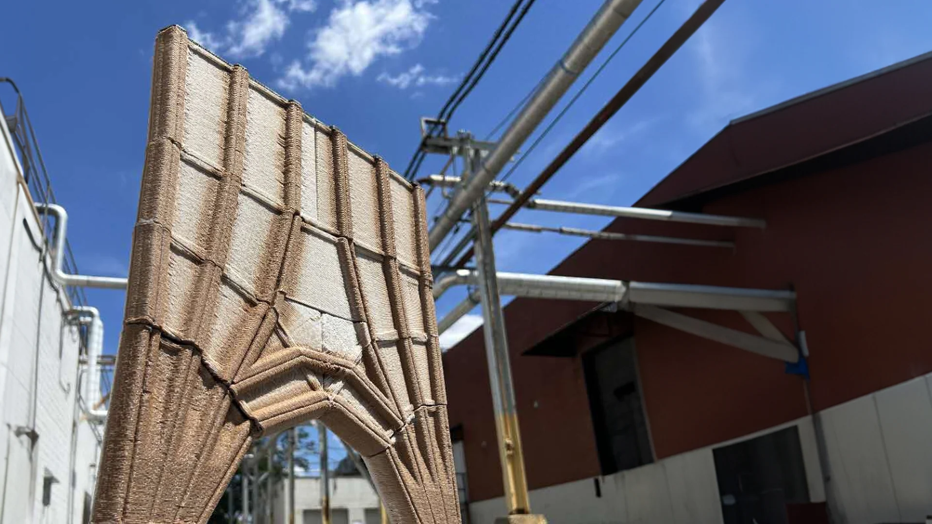
The column study starts from a funicular polyhedral geometry designed with 3D graphic statics. An intersecting geometry transfers the positions of its compression members onto a continuous envelope. Dividing that envelope assigns wood-fiber-reinforced PLA to the member regions and lightweight foaming filament to the spaces between them.
The 250 mm prototype explores how structural regions and an infill intended for insulation can share a continuous printed surface. The photographs compare the multimaterial print with the earlier concrete geometry. The case documents material placement and fabrication; the paper does not report a thermal test or a structural load test of this printed column.
Surface division: making a stress field visible
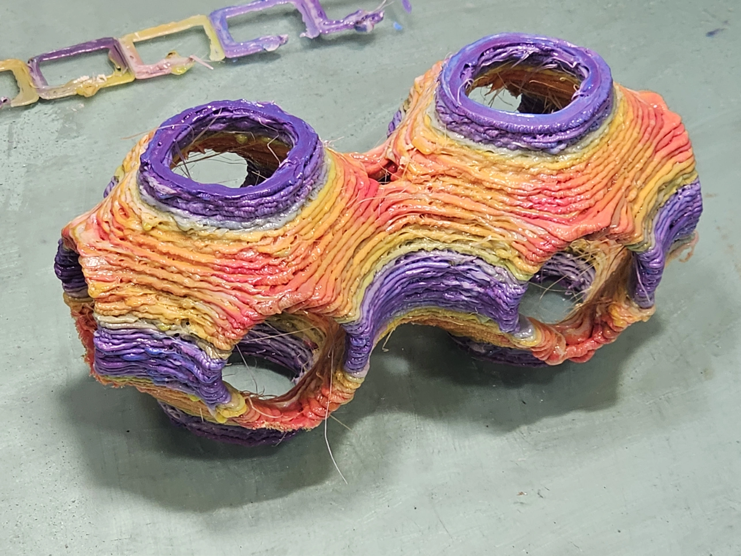
A triply periodic minimal surface (TPMS) provides a second three-dimensional case. Finite-element analysis under a simulated 50 kN vertical load generates a stress field. Sampling that field assigns blue PLA to low-stress regions, green to intermediate regions, and yellow to high-stress regions.
The print turns the numerical field into a physical color distribution on the complex surface. The 50 kN is the simulation input; the case demonstrates the placement of three colored PLA filaments, without reporting that load as a tested capacity of the printed object.
Additional experiments and design studies
Material fidelity and the scope of the system
The hardware, transition model, and three assignment strategies give designers control over both the intended mixture and the position of its transition. Finite mixing lengths set a limit on how quickly composition can change, and viscosity differences affect the predictability of a material pair. Auger speed must be calibrated together with flow, cross-section, and the desired interface behavior.
The research establishes a prototype workflow through gradient measurements, interface tests, a structural comparison, and printed design cases. Extending it to architectural assemblies requires component-specific mechanical and thermal validation, as pursued through the related truss and insulation research.
Evidence & scope
The published study combines a numerical description of mixing, experiments on deposited composition, and six design case studies. These establish the workflow under the tested material and printing conditions; the performance of an architectural assembly requires further component-specific testing.
Related publications
All publications →-
Published in Materials & Design 249 (2025), article 113479. The paper presents the printhead, transition model, validation experiments, and six design case studies. Figures 2, 4, 5, 7, 8, 10, and 11 are reproduced below from this study.
Prototyping high-fidelity multifunctional objects using single-nozzle multi-filament additive manufacturing system with active mixing
Materials & Design · 2025