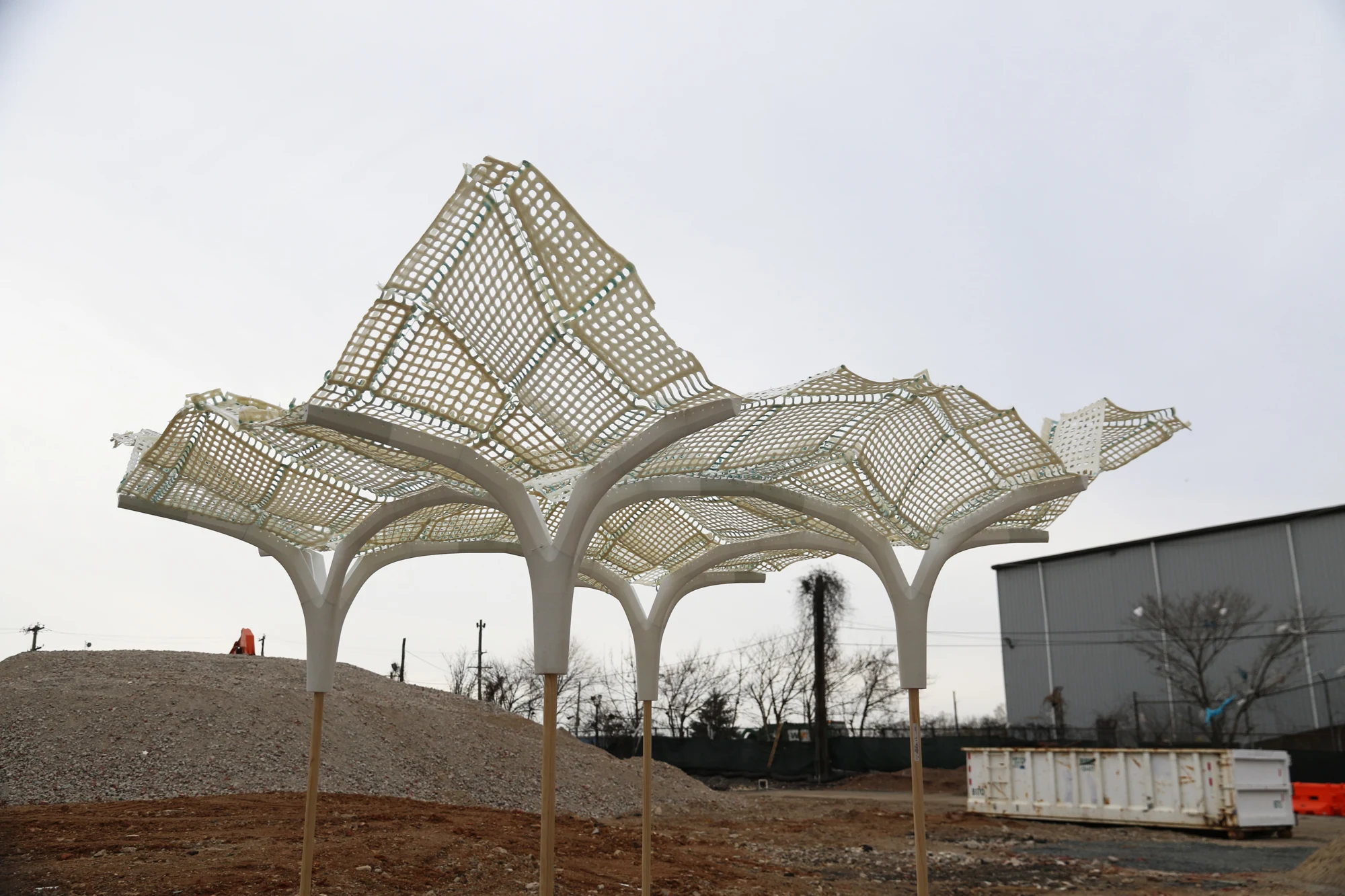
A 1:10 paper shell and 1:25 PLA-on-fabric prototype demonstrate reconstruction. Full-scale plywood formwork and concrete casting remain proposed. View evidence ↓
Thin sheet: reconstructing the shell in paper
A 1:10 Bristol-paper model, measuring 650 × 650 mm, assembles the shell from 21 pieces. Laser-cut dashed lines allow both mountain and valley folds. Gluing the tucks fixes their 180° creases and joins the pieces into the slab.
Comparison with the digital target shows qualitative geometric agreement. Thin or long, narrow tucks provide weaker control of the folded shape; the isolated model also requires horizontal support at its outer boundary. The glued assembly demonstrates reconstruction but cannot be unfolded for reuse.
The 1:10 paper prototype: laser-cut patterns, folding, glued modules, and the assembled slab in plan and elevation.
Thick sheet: beveled panels and fabric hinges
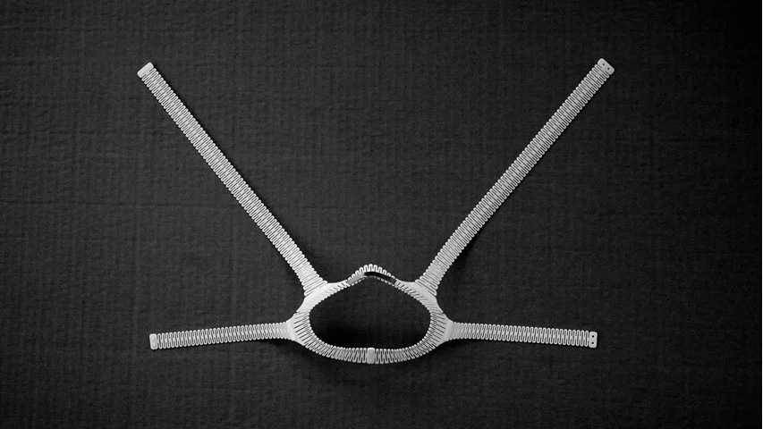
Finite material thickness introduces collisions at a fold. Beveled panel edges encode the required angles, while a continuous fabric layer acts as a hinge. A 1:25 prototype uses PLA printed directly onto gold tulle mesh, divided into 13 pieces. A 0.1 mm offset on each side of the 180° creases prevents adjacent faces from fusing during printing.
The printed components fold into the target curvature and can be unfolded without damaging the fabric hinges. This prototype demonstrates thick-sheet geometry and reusable folding; it was not used to cast concrete.
The 1:25 PLA-on-fabric prototype, from flat printed pieces to folded modules and assembled formwork.
From force diagrams to foldable geometry
PolyFrame 2 generates a planar-faced shell through reciprocal force and form diagrams. A modular slab is organized into a column, canopy, and connecting arches. Subdivision controls the panel network and curvature: the column and canopy regions are synclastic, while the arches are anticlastic. These differences determine where the shell is split before flattening.
Force cells and their corresponding shell regions (left); synclastic and anticlastic vertex configurations (right).
Four force-diagram subdivision patterns and their corresponding shell layouts.
Tucks compensate for flattening
Unfolding a doubly curved panel network creates gaps, overlaps, and rotational mismatch. A tuck inserts a local fold region that absorbs this mismatch when the sheet is refolded. Its central crease closes through 180°, while neighboring creases recover the target surface angles.
Tuck widths are coupled by closure relationships at shared vertices. Compression-force data guides their distribution within limits set by material thickness, fold collisions, machine-bed dimensions, and assembly. Splitting along the anticlastic arch regions separates demanding curvature into manageable pieces.
A proposed route to concrete shell construction
A 10 × 5 m outdoor gallery pavilion applies the system as a modular shell canopy. The proposed construction sequence combines CNC-cut plywood ribs with fabric membranes, transports the components flat, and folds and assembles them for casting. Repeated modules would provide neighboring support; a standalone canopy requires lateral bracing.
Full-scale plywood fabrication and concrete casting remain future work. Geometric tolerances, stiffness, casting pressure, waterproofing, demolding, and hinge durability require quantitative testing.
Proposed fabrication, transport, assembly, and casting sequence (left); pavilion renderings, plan, and section (right). The pavilion is a design proposal.
Related publications
All publications →-
Accepted for ACADIA 2026 · Conference in October 2026
Tuck-Folding: A Computational Method for the Flattening and Fabrication of Compression-Dominant Shell Structures
Research manuscript · 2026