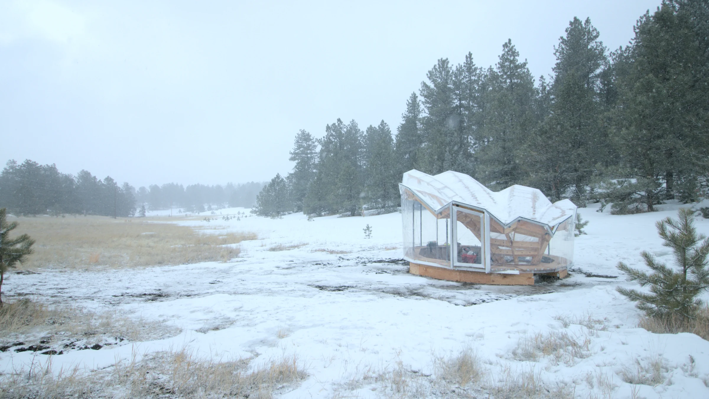
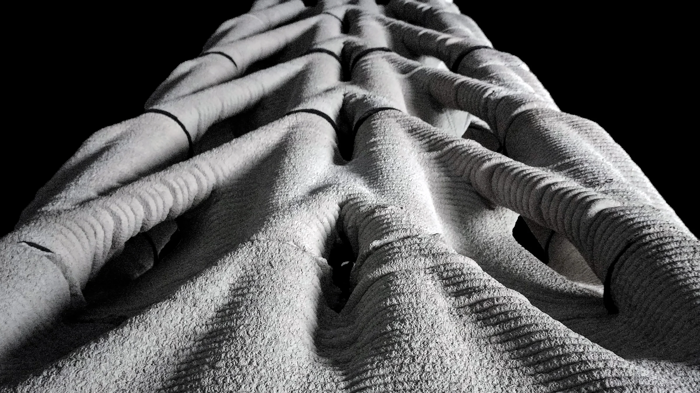
The completed pavilion, assembly film, structural diagrams, prototypes, and construction records document a shared student-built outcome. View evidence ↓
Building collaboration
TRI-ARC is a full-scale campus pavilion developed by fifty graduate students and three faculty members during a ten-week summer design-build studio at Lawrence Technological University. Eight weeks of remote collaboration preceded six days of on-site construction. Shared digital models, component families, fabrication protocols, and assembly manuals allowed a distributed cohort to coordinate a single built work.
The studio’s teaching proposition connected equilibrium to collective decision-making. Member dimensions affected steel plates; plate geometry affected routing and drilling; fabric patterns depended on tubular frames; and furniture had to accommodate both people and structural ballast. Students reorganized from proposal teams into specialized structure, joinery, cladding, ground, furniture, graphics, model, and preparation groups as the project moved toward construction.
University purchasing could begin only five days before Build Week. This constraint made readily available stock materials and in-house fabrication central to the design. Underground utilities required a foundation without excavation, while the installation needed to remain modular and movable. Standard lumber, customized connections, prefabricated assemblies, and furniture-integrated ballast emerged from these combined procurement, site, and construction requirements.
| Built system | Extent |
|---|---|
| Overall dimensions | 30′6″ × 17′7″ × 11′0″ high (approximately 9.3 × 5.4 × 3.35 m) |
| Timber structure | 12 branching trusses; 264 linear members |
| Primary connections | 106 plasma-cut steel joints; 144 CNC joint covers; approximately 1,200 bolts |
| Post-tensioning | 3 primary cables; 4 secondary cables |
| Cladding | Blue and white textiles on EMT frames; 70 3D-printed joints |
| Furniture | 15 seating modules; 14 planters; 2 tables |
| Studio | 50 students; 3 faculty; 6 days of on-site construction |
Method
Three mutually supporting arches connect an equilibrium network to a coordinated system of timber trusses, steel joints, textile panels, and furniture-integrated ballast. Shared component families and assembly protocols allow specialized teams to work on interdependent parts of the same structure.
Negotiating a shared design
Nine student teams developed precedent-based proposals for lightweight structures, modular assemblies, and shading systems. These teams consolidated into three groups to test site-specific schemes before selecting one proposal for development. The resulting three canopy zones gave structure, cladding, furniture, and ground teams a shared geometry through which to coordinate their work.
Form and force
Polyhedral three-dimensional graphic statics (3DGS) generated three mutually supporting arches arranged triangularly in plan. Reciprocal form and force diagrams developed the spatial network through equilibrium; twelve branching timber trusses materialized that network. Timber sections responded to force demand, while stress-informed steel plates connected structural analysis to connection design.
The line-based network leaves fabrication tolerances, finite member dimensions, joint rigidity, and support compliance unresolved. TRI-ARC carries these conditions into the design through differentiated components and a force state that can be adjusted during assembly.
Activating equilibrium through post-tensioning
Three primary cables stabilize the arch systems; four secondary cables control the extended cantilevers and contribute resistance to lateral and eccentric loading. This hierarchy links global equilibrium to local geometric control.
Assembly separates four construction states: the erected timber frame, primary-cable tensioning, secondary-cable tensioning, and the completed canopy. The cables were tensioned before installation of the non-prestressed fabric, allowing students to observe structural activation before the cladding introduced its environmental loads.
Designing for gravity and wind uplift
Michigan is exposed to severe thunderstorms and tornadoes, with extreme tornado events producing estimated peak winds of 150 mph or more. For a lightweight canopy, pressure differences across the upper and lower surfaces can generate uplift exceeding the structure’s self-weight, while uneven wind loading can cause overturning. The design must therefore address both downward gravity loads and upward wind loads, including possible reversal of forces within a structure shaped initially for compression.
In TRI-ARC, wind loads collected by the textile panels pass through the EMT frames and their connections into the timber trusses. The cable hierarchy stabilizes the frame and controls cantilever response, while connections between the truss bases and furniture-integrated ballast establish a continuous hold-down load path. The weight and distribution of the ballast help resist uplift and overturning without excavated foundations.
A foundation without excavation
Underground utilities prohibited excavation and conventional foundations. Precast deck blocks bear on compacted aggregate, while ballast concealed within furniture connects directly to truss-base assemblies to resist uplift. A laser level established a common datum across the sloping lawn.
The site layout avoids existing trees, connects adjacent sidewalks, and incorporates flush-set pavers. Removed turf was retained and replanted after construction. Bolted assemblies and non-penetrating supports allow the installation to be disassembled and relocated.
Site layout, deck-block supports, aggregate bedding, and ground interfaces.
Standing through a Michigan tornado
TRI-ARC remained standing through a Michigan summer tornado, with reported maximum wind speeds reaching 90 mph (145 km/h). The footage below records the completed pavilion during the storm.
On-site storm footage. Reported maximum storm wind speed: 90 mph.
Standard lumber, customized joints
Three truss families organize twelve branching frames made from standard dimensional lumber. Geometric complexity is concentrated at connections, where customized joints accommodate changing member orientations and force demands.
Primary joints sandwich CNC-plasma-cut steel plates between routed timber members and CNC-milled joint covers. Upper connections incorporate lateral bracing and cable attachment points; secondary assemblies use 3D-printed ASA connectors. This hierarchy assigns different materials and fabrication processes to the demands of each interface.
Truss detailing and steel-plate geometry translate structural demand into fabrication information.
Textiles as an assembled system
Blue trapezoidal and white triangular textile panels are supported by lightweight electrical metallic tubing (EMT) frames. Bent stock tubing, 3D-printed ASA connectors, and off-the-shelf fittings produce the required geometries from readily available components.
CNC-cut templates standardize fabric cutting; reinforced pockets and edge binding coordinate the textiles with their tubular frames. Dry-fitting revealed discrepancies between sewn panels and EMT assemblies, prompting revisions to patterns, connections, and the installation sequence.
Panel geometry, fabric templates, connectors, and the cutting, bending, and assembly sequence.
Furniture, ballast, and material reuse
Fifteen seating modules, fourteen planters, and two tables extend the canopy’s triangular geometry to the ground. Furniture enclosures conceal ballast tied to the truss bases, so spaces for occupation also resist uplift.
Students deconstructed previous design-build installations and salvaged plywood for furniture facing boards. Refinishing this plywood and reusing existing sandbags connected the new pavilion to an ongoing cycle of studio construction. Bolted, modular components support later repair, relocation, reconfiguration, and reuse.
Design for manufacturing
Square-cut timber ends simplified processing, while CNC-generated routing and drilling jigs standardized work across fabrication stations. Prototypes exposed tolerance differences among plasma-cut steel, routed timber, and manually cut lumber. Students revised cutting, routing, and drilling operations before producing the full component families.
Shared fabrication drawings, component identifiers, and assembly instructions connected the digital model to workshop tasks. Procurement, geometry, and production capacity remained coupled: changes to a joint affected its cutting file, timber preparation, hardware, and assembly sequence.
Repeatable truss families and joint toolpaths define the fabrication packages.
From prototypes to coordinated production
Students moved between mockups and production, checking steel-to-timber fit, bolt alignment, and the assembly of repeated members. Routing fixtures and joint covers made local tolerances visible and repeatable across workstations.
A full truss prototype and the prepared timber components.
Prototype connections and repeated CNC-milled joint covers.
CNC routing and digitally fabricated connection components.
Parallel steel-connection and textile-panel production.
Six days on site
The six-day Build Week brought the remotely coordinated work into full-scale assembly. Lower members were secured to the foundations before upper members were raised and connected. Primary and secondary cables were tensioned in sequence, followed by the non-prestressed cladding.
Site preparation, furniture construction, frame erection, and textile installation required teams to resolve their interfaces together. The assembly sequence made the relationship between support conditions, cable tension, cantilever geometry, and cladding installation directly observable.
Establishing the ground supports and erecting the timber frame.
Structural research beyond construction
The built canopy extends the original research question: how does staged post-tensioning preserve a compression-dominated equilibrium network after it becomes a structure with finite sections, joints, fabrication tolerances, and compliant supports?
The evaluation framework compares the four construction states using nonlinear beam-and-cable models under self-weight, snow, symmetric uplift, and asymmetric uplift. Displacement, cantilever-tip deflection, cable forces, support reactions, and the balance of axial and bending strain energy provide measures of each cable hierarchy’s effect. Joint stiffness, cable prestress, and support compliance are sensitivity variables; geometric surveys and non-destructive field loading provide a route for calibration.