A working 36-actuator bed, custom control boards, and initial robot-printing tests demonstrate reconfiguration; structural performance of prints is not established. View evidence ↓
Pinbed is a reconfigurable printing bed for robotic additive manufacturing. Inspired by multi-point forming, it uses an array of independently driven pins to generate different nonplanar support surfaces from a digital model.
Developed in 2020 as part of my master’s research at Cornell University’s Jenny Sabin Lab, the project connects mechanical design, custom electronics, and Grasshopper control in one fabrication system. I led the prototype development, including its construction, wiring, programming, and initial printing tests.
Prototype and printing tests
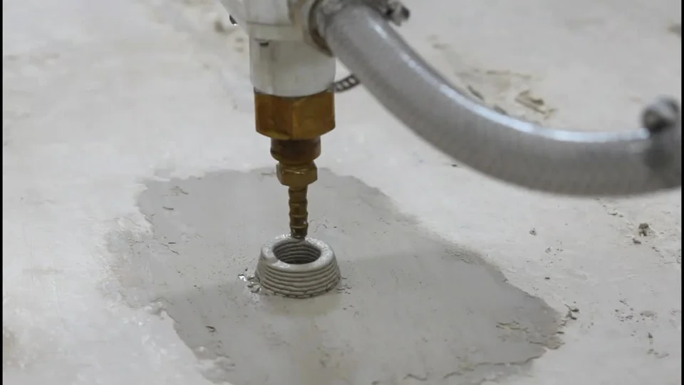
Initial printing tests — the robot and assembled printbed (left), and the deposited component supported by the bed (right).
Assembly — the 6 × 6 actuator array mounted in its wooden frame, before the flexible printing surface is installed.
Structure and actuation
The prototype has an approximately 30 × 30-inch working area and 6 inches of vertical travel. Its 36 linear actuators form a 6 × 6 grid. Flexible metal strips span the actuator heads and support a cast silicone-rubber printing surface, translating the individual pin heights into a continuous bed.
Each actuator combines a 12 V DC motor, an 11.5:1 geared reducer, and a lead screw. A magnet and Hall-effect sensor register motor rotation, allowing the controller to estimate actuator travel. The frame carries the actuator holders, power supply, and control modules, with wheels for moving the prototype within the lab.
Assembly wiring (left) and the labelled mechanical configuration (right), including the flexible surface, actuator mechanism, frame, and electronics.
Electronics and Grasshopper control
I designed and fabricated three PCB-based control modules, each serving 12 linear actuators. H-bridge drivers control the DC motors, while Hall-effect feedback records their rotation. The modular arrangement was intended to allow additional actuator groups to be connected for a higher-resolution bed.
I also developed a Grasshopper plugin that samples a target surface into a 6 × 6 grid and converts the sampled heights into actuator commands. A wireless serial connection links the computer to the Arduino-based modules, carrying motor-speed and rotation-count commands.
Control-module circuit design (left) and the Grasshopper interface for translating surface geometry into actuator heights and motion commands (right).
Reconfiguration and the robot workflow
The same digital surface provides both the target bed geometry and a reference for generating the robot’s printing toolpath. At each deposition position, the end effector is oriented to the local surface normal. This shared geometry coordinates the adjustable support surface with the robot’s motion.
The GIF shows the actuator array changing configuration alongside the robotic arm. The accompanying diagram traces the connection from Grasshopper through the serial link, Arduino, motor drivers, and Hall-effect feedback, alongside the robot-control branch.
Reconfiguration demonstration (left, looping GIF) and the software–electronics–robot communication workflow (right).
Research scope
The work produced an assembled and programmed printbed, custom control electronics, a Grasshopper interface, and initial printing tests. It explored a reusable support surface for curved deposition as part of my master’s research into bio-inspired architectural geometry. Fabricating larger architectural components remained a direction for further development at this prototype stage.
Related publications
All publications →-
Interactive Fabrication and Design of Bioinspired Surface Geometry
Cornell University · 2021